The PWM (Pulse Width Modulation) signal is well known in the art of communication. The value of the transmitted signal is «encoded» in the transmission by means of a two-state signal (voltage) as the ratio between the on/off states. This ratio is called a shift. The cycle in which one shift is transmitted is called the period, and it ranges in fractions of a second to microseconds. Using a PWM signal, a relative value in the range of 0 to 100% is transmitted. It is therefore a kind of very fast «flashing» with a variable flashing length and constant frequency. The PWM signal is used in radio engineering for modulation of the communication signal, in electrical engineering for power control of motors, dimmers and other power elements.
Signál PWM se však v systémech řízení budov vyskytuje také v trochu jiné podobě. Zde se používá k ovládání tepelně ovládaných ventilů. Zde bychom měli poukázat na rozdíl mezi pohonem:
- Termální (elektrický pohon, ovládá se signálem zapnuto — vypnuto nebo jen PWM, sám nemá ovládací funkci) a
- Termostatický (usually a mechanical principle, it works as a regulator with a P-characteristic, it opens the valve so that the set value is maintained on its sensor).
Ačkoli jsou termopohony v zásadě také dvoustavové řízení, protože signál nabývá buď plné hodnoty (24 V AC nebo 230 V AC, podle typu) nebo 0 V, «dvoustavovým řízením» rozumíme systém ve kterém je pohon buď plně otevřen nebo zcela uzavřen v ustáleném stavu. Pulsně modulované řízení PWM se někdy také nazývá kvazi-kontinuální řízení, protože analogový signál se nepoužívá k přenosu energie a informací, ale tento «bliká» s proměnným střídáním. Perioda signálu PWM je (na rozdíl od komunikačních technologií a průmyslu) v systémech řízení budov několik desítek sekund. Tím se snižuje spínací frekvence výkonových prvků, což může mít pozitivní vliv na vyzařované elektromagnetické rušení. Nicméně termopohony fungují uspokojivě díky delší časové konstantě: doba potřebná pro plný zdvih ventilu je mezi 2.5 a 6 minutami při 100% signálu.
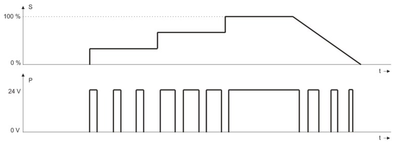
Fig. 1 — PWM signal, S: signal magnitude, P: PWM output voltage for 24 V AC
The principle of operation of the thermal valve is as follows: The heating element is heated by a passing current from the PWM control signal. The generated heat acts on an element made of a material with high thermal expansion, which changes its volume and presses on the valve stem the more it is heated. By changing the shift of the control signal, we can then change the degree of opening of the valve and thus the flow of heating or cooling medium essentially. The valves have a steady state consumption of around 3 to 6 VA, depending on the type, control force and control voltage.
An important feature of the thermal drive is the delay of the reaction when opening from a cold state. After connecting the supply voltage, it takes a minute or two for the drive to react and start moving — see the first part of the curves in Fig. 2, where we see that during the first 2.5 to 3.5 minutes, when the 100% signal is applied, valve completely closed. Only after the mechanism has warmed up does the stem start to move and the valve does not open completely until another tens of seconds. In practice, this phenomenon is unpleasant for heating convectors, which circulate cold air in the room for the first few minutes after the start of the transition from the attenuation mode to the day mode, which is not comfortable in the winter. As a countermeasure, either the drive is continuously preheated by intermittent pulses even in damping mode to reduce the ramp-up interval to a minimum, or a fan start delay of about 3 minutes is introduced, after which the valve is already at least partially open and hot flows in the register. water.
Tepelný pohon má také tu vlastnost, že správně funguje pouze při okolní teplotě do cca. 40 °C. Při vyšších teplotách není zaručeno úplné uzavření mechanismu, protože může dojít k podtečení ventilu. Proto buďte opatrní při instalaci servomotorů do rozvodných skříní a podobných uzavřených nebo tepelně izolovaných prostor.
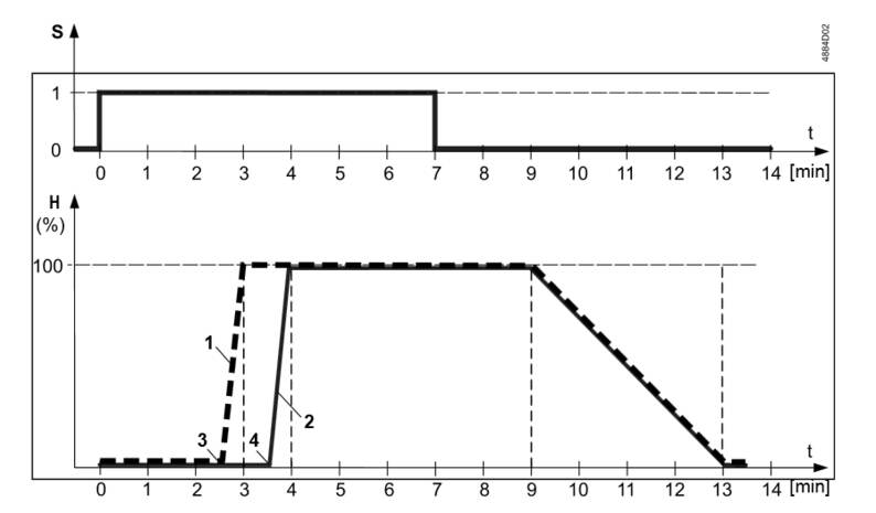
Fig. 2 — Valve stroke to actuator supply voltage over time. S: actuator voltage, H: valve stroke, 1: actuators at 230 V AC, 2: actuators at 24 V AC, 3.4: start of valve opening. (Source: Siemens)
The PWM signal can be found on electronic room thermostats, fan coil controllers, cooling panels and convectors, but also on output modules. A triac is usually used as a power member. When designing, we often address the question «how many valve actuators can be connected to one triac output?» Regulators usually have the maximum permissible triac current in the documentation. However, it is necessary to realize that thermal drives have several times less resistance in the cold than in the steady state, and therefore the initial current is several times greater than the continuous current. We must therefore respect this higher value of the initial current. When connecting multiple drives to one controller, we have several solutions:
- Spojení master-slave, if used by the controllers. Then as many controllers as there are in the convector or fan coil zone are installed, and the controllers are configured so that one of them (master) controls the outputs of the others. The advantage is the possibility of switching to several independent zones when changing the spatial arrangement of the room, the disadvantage is the higher price of this solution.
- Triac amplifiers (eg Domat ME210, ME220, Siemens UA1T, or the use of solid state relays (SSR) of various types and powers (Carlo Gavazzi, etc.)). These are probably the most common and cost-optimal choice. Pay attention only to the sufficient dimensioning of the supply conductors so that voltage drops of more than approx. 10%. With larger drops, the power at the valves decreases with the square of the voltage! The resulting smaller valve opening is usually «tightened» by the PI algorithm of the controller, but the problem could occur at peak times, when we need the registers to provide maximum power when the valve is fully open. Do not use conventional electromagnetic relays instead of triacs or SSRs. These are only suitable for two-state control, even in an emergency (sufficient hysteresis must be set for the controller — and adjustable).
- Use of 230 V AC valves, which have a smaller operating current and therefore it is possible to connect more to one triac. Again, we must pay attention to the peaks of the initial current: for example, with the Honeywell MTx-230LC poh drive, the continuous current is 10 mA, while the initial current during the first 500 ms is 400 mA, ie forty times the continuous value. Circuits with PWM heads must be adequately secured.
When controlling several heaters with a single signal, the radiators do not work at full power most of the time. When heating at 20 to 30% of output, there may be a situation where, due to uneven hydronic conditions in the heating system, some of the bodies heat up a bit and some do not. The total power supplied to the room precisely covers the losses, so the regulation works properly. However, the user does not like this condition, because «some radiators do not heat» — against this, however, it is difficult to do anything other than enlightenment.
The control algorithm usually has a common PI characteristic, the requirement 0… 100% is fed to the PWM modulator, the output of which is controlled by a triac. However, good results can also be achieved with radiator control with two-state control with minimum hysteresis in tenths of K, mostly due to the inertia of the heating element.
During service and commissioning, we need to check whether the controller output provides an output signal. In doing so, the output must first be brought to the active state. This is usually done by increasing the setpoint (for heating) or decreasing it (for cooling). This works well for two-state or analog outputs, but for PWMs less than 100%, the state of the triac may still depend on what part of the period the output signal is currently in. In addition, the internal PI (D) algorithm can change the output signal so that a full signal (100%) appears at the output for up to a few minutes. Due to the length of the period (tens of seconds), it is easy to evaluate the state when there is no voltage at the output during the measurement, by mistake as a triac failure. Conversely, when measuring with high-impedance multimeters, we sometimes measure an oscillating voltage on a closed triac that is not connected to the valve drive, which may give the impression that the output is active. It is therefore recommended to use, for example, an LED diode with a series resistance of approx. 2k2 for 24 V AC or even better low-power indicator lamps (for 24 V or 230 V AC). Some drives, eg Siemens ASY23-LD, already have an indicator LED in the body, which lights up in the presence of control voltage. The light indication facilitates diagnostics even in cases where we check the voltage on the valve head, which is located at the opposite end of the room from the regulator. This reveals, for example, cut or incorrectly connected cables in the floor.
Some controllers (eg Domat UC100, UC200, FC010) also have a so-called resuscitation mode: if the control knob is pressed for a few seconds while the power supply is connected to the controller, the device switches to a state where the outputs are not controlled by control algorithms but manually — by setting the knob. In this way, we can manually bring each output to a permanently active state and conveniently measure the voltage on the drives. The activity of the outputs is also indicated on the LCD display. They can also be manually controlled by a relay for controlling the fan coil.
A common design problem is that the fittings, even with actuators, are supplied by a heating engineer or a supplier of convectors or fan coils — and the controller is supplied by the M&R profession. Then it is necessary to arrange an interface:
- drive supply voltage: 24 or 230 V. For reconstructions where old 230 V drives remain with the technology and the controller has a 24 V output, a triac converter (eg Domat PWR011) can be used,
- smysl otevření: NC (Normally Closed) or NO (Normally Open). With some controllers, the opening direction can be set in software, but rarely separately for heating and separately for cooling! It is therefore necessary to coordinate the supply of heaters and air conditioning, especially if the controller is to control radiator heating and cooling fan coil,
- initial and continuous drive,so that designer correctly determines the load on the outputs and, if necessary, uses output signal amplifiers.
Pokud jsou pohony a armatury pro řízení a měření dodávány jinými profesemi, je situace složitější a musíme specifikovat:
- max. drive stroke (v mm)
- min. actuator control force to reliably open the actuator even at critical piping conditions
- spojení (today usually thread M30 x 1.5 mm)
- or the dimensions of the head, so that the actuator can be installed at all to the valve and fit, for example, between the valve and the wall.
Protože jsou tepelné ventily v instalacích vždy přítomny ve větším množství (v desítkách až stovkách stejných kanceláří nebo místností), každá chyba s sebou nese vysoké náklady na výměnu a časové ztráty v důsledku dodacích lhůt. Protože tepelné ventily v instalacích jsou vždy přítomny ve větším množství ( v desítkách až stovkách stejných kanceláří nebo místností), každá chyba s sebou nese vysoké náklady na výměnu a časové ztráty v důsledku dodacích lhůt.
Special output modules, such as the Domat M312 with 8 triac outputs at 24 V AC, can facilitate work with PWM-controlled drives. After the RS485 bus with the Modbus RTU protocol, a value of 0… 100% is sent to the registers for individual outputs and the PWM signal is generated directly in the module. The default PWM signal period is 100 s, and this value can be changed via the bus. The M313 module is used to control heads with 230 V AC supply. The modules are especially suitable for installation in distribution boxes, because it is not necessary to route cables from the room controllers to the thermal drives that are installed in the boxes. Requests to open valves are read via the bus and sent to the module after communication using input-output variables.
Závěrem je třeba poznamenat, že pohony se signálem PWM jsou zcela nevhodné pro ovládání ventilů vzduchotechnických jednotek s úpravou venkovního vzduchu. Na ně potřebujeme reakční dobu v řádu max. Desítky sekund pro zaručení správné funkce protimrazové ochrany. Není funkčním řešením ani pro malé jednotky s ventily např. DN25, pro které existují termopohony odpovídajících rozměrů a sil. Tepelné akční členy s PWM řídicím signálem tedy poskytují spolehlivé a cenově dostupné řešení ovládání zónových zařízení, avšak pouze v případě, že jsou správně navrženy, instalovány a uvedeny do provozu.
Experiment with PWM and servo angle to understand the relationship and explore other aspects of Servo motor control in a hands-on approach.
Puneeth
Mar 5, 2023 • 7 min read
Úvod
The Servo motor is a versatile device used for motion control in electromechanical projects. You can use it in various fields, including robotics, medical devices, and security.
The Servo motor uses only one IO pin to control the position. You can understand the basics of servo motor control by monitoring it using the Wokwi logic analyzer. The logic analyzer is a simulated instrument that shows the voltage status on the pins, measures pulse widths, observes timings between two events, and more!
This article is part of the blog series on understanding UART, SPI, I2C, PWM, WS2812 protocols, and more in a hands-on approach using the logic analyzer.
Základy servomotoru
How does a Servo motor work?
A servo motor is an electromechanical device. It has an electronic board that accepts PWM (Pulse Width Modulation) signals and measures its on-time pulse width. The servo motor also has a potentiometer that helps in keeping track of the shaft position.
The embedded board continuously detects and corrects the unintended shift in the shaft position. The target position is maintained by continuous error correction between the shaft position and the user input.
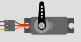
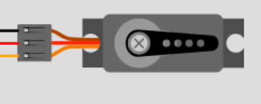
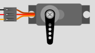
Na obrázku níže vidíte velmi běžný hobby servomotor. Má tři kolíky:
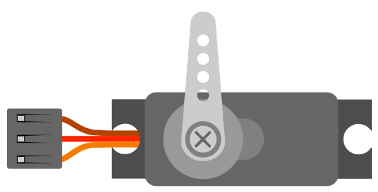
| Jméno | Barva drátu | Popis |
|---|---|---|
| PWM | Žlutá | Input control signal for the motor |
| V+ | červená | Kladný napájecí terminál |
| Země | Hnědý | Uzemňovací terminál |
Pro ovládání servomotoru vysíláte PWM signál s frekvencí 50 Hz. Obvyklá frekvence může být mezi 40 Hz a 400 Hz.
Why would one pick 40 Hz over 400 Hz ? (or viceversa)
As you increase the frequency of the PWM signal, the time given for the servo to reach new posistion reduces. 400 Hz implies a latency of 2.5 ms versus 25 ms latency ( 40 Hz ). It’s a tradeoff between better precision( 40 Hz ) and faster operation( 400 Hz ).
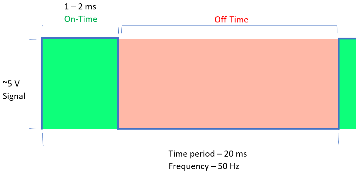
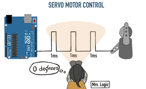
You can rotate the servo motor shaft from 0° to 180° by varying the PWM pulse width from 1 ms to 2 ms .
Here’s a cheat sheet for the shaft’s position in a typical hobby servo motor:
- » 0° » ( ~1 ms pulse)
- » 90° ” (pulz ~1.5 ms)
- » 180° » ( ~2 ms pulse)
Věděli jste?
Continuous servo motors are a type of servo motor that can rotate a full 360 degrees continuously in either direction rather than moving to only specific positions. In this case, you can control the direction but not the position using PWM.
Monitoring the Servo motor signal on the Wokwi logic analyzer
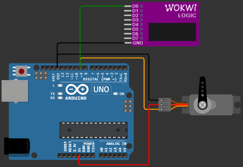
You can start faster with a pre-built Servo motor project. The control signal of the servo motor is connected to Pin 9 of the Arduino and D0 of the logic analyzer. The brown wire goes to ground, while the red wire is connected to Arduino’s 5 V source.
Pro snadný postup krok za krokem pro nastavení logického analyzátoru a čtení dat si přečtěte článek Úvod.
Let’s drive the stepper motor to 0° , 90° , and 180° and observe the waveform on the Servo control signal pin.
Case 1: Servo at 0° position
Copy and paste the below code into the editor window of the prebuilt project above.
#include Servo myservo; // create servo object to control a servo int pos = 0; // variable to store the servo position void setup() < myservo.attach(9); // attaches the servo on pin 9 to the servo object >void loop()
The line below sets the servo motor’s shaft position.
myservo.write(0); Run the simulation and observe the servo motor’s shaft position. It’s now in the extreme left position, as shown in the image below.
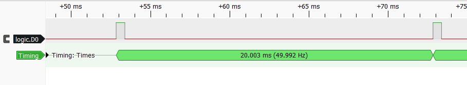
Observing the pulse width of the PWM signal using the logic analyzer data shows that the ON width is about 0.5 ms .
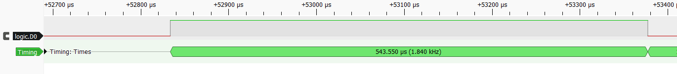
The frequency is about 50 Hz .
You might have heard PWM and PPM terminologies associated with the Servo motor. PPM stands for Pulse Position Modulation.
Všimli jste si, že úhel servomotoru závisí pouze na době zapnutí signálu? I když změníte frekvenci z 50 Hz na 100 Hz, úhel servomotoru zůstane stejný. Servomotor tedy není skutečným zařízením řízeným PWM.
PWM conveys the information on the power delivered which doesnt reflect in the servo motor position.
take an example — A PWM signal with 2 ms on time and 2.5 ms period ( 80% dutycycle), delivers more power than a PWM signal with 2 ms on time and a 50 ms period ( 5% duty cycle).
The servo would resond in the same way for both PWM signals.
Case 2: Servo at 90° position
Update the parameter you send in the myservo.write function to turn the servo motor by 90° .
myservo.write(90);Spusťte znovu simulaci a podívejte se na polohu servomotoru. Nyní je ve středové poloze.
Let’s now observe the pulse width of the PWM signal using the logic analyzer data that corresponds to the center position of the motor.
The ON width is about 1.5 ms .
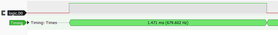
The frequency is still 50 Hz ( 20 ms ). The frequency never change. Only the PWM on time pulse width changes.
Case 3: Servo at 180° position
Update the parameter you send in the myservo.write function to turn the servo motor by 180° .
myservo.write(180);Spusťte znovu simulaci a podívejte se na polohu servomotoru. Nyní se posunula do krajní pravé polohy.
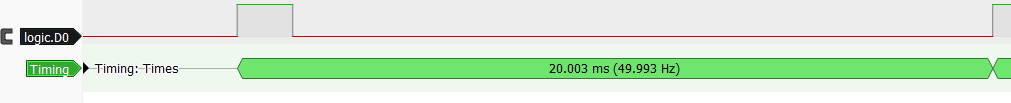
Now, please look at the PWM signal’s pulse width using the logic analyzer data that corresponds to the extreme right position of the motor shaft.
The ON width is 2.4 ms .
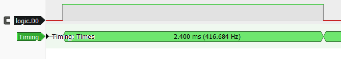
The frequency is still 50 Hz ( 20 ms ). No change in the frequency.

Všiml sis?
The pulse width expected was 2 ms for a rotation of 180° , but we measured 2.4 ms here. The actual pulse widths vary by type and make of servo motor. You may even notice the differences in the same batch of servo motors. Depending on the precision you need, you may have to calibrate the servo motor first, one time.
Bonus section — Servo motor with feedback
A servo motor includes feedback circuitry that helps the motor to continuously adjust the shaft position. Specific servo motors also feature an additional fourth line that outputs an analog value indicating the current shaft position.
Servomotor řídí polohu hřídele na základě šířky pulzu PWM, ale proč bych měl stále číst zpětnou vazbu, když se řídicí obvody serva již starají o přesnost polohy?
The additional feedback signal is useful in many situations.
Nedostatečný výkon — Insufficient power to drive the load can cause the servo motor to stop at a position other than the intended one.
Proč by se to stalo? K tomu může dojít, pokud napájení motoru není dostatečně silné, aby překonalo odpor zátěže, což způsobí zastavení nebo zastavení motoru před dosažením požadované polohy.
Mezi další faktory, které mohou způsobit tento problém, patří nesprávné nastavení napětí⚡ nebo proudu, mechanické problémy s motorem nebo zátěží a elektronické problémy s řídicím obvodem.
Problém s kabeláží — Jedním z potenciálních problémů, které by mohly způsobit zastavení servomotoru v nesprávné poloze kvůli nedostatečnému napájení, je odpojený ovládací vodič. To může být obtížné zjistit u třívodičového serva, protože neexistuje žádný přímý způsob, jak zkontrolovat stav připojení.
Ušetřete čas — Here is the snippet of the prebuilt project. We set the target position using myservo.write() . Did you notice that we had given a delay right after setting the position?
myservo.write(pos); // tell servo to go to position in variable 'pos' delay(15); // waits 15ms for the servo to reach the positionVíte co, zpoždění je pro náš servomotor důležité. Potřebuje dostatek času, aby se dostal tam, kam směřuje. Pokud tomu nedáme dostatek času, nedosáhne cílové pozice, a to prostě není dobré. Představte si, že ve složitém projektu neaktivujete spínač nebo pouze částečný pohyb z robotické paže.
Ale na druhou stranu, pokud tomu věnujeme příliš mnoho času, jen ztrácíme čas a celá operace bude pomalejší. Takže je to všechno o nalezení toho sladkého místa.
Feedback pin can be a lifesaver in this situation. Here’s the deal, you set the target position and then start keeping an eye on the feedback pin. Once you’re sure that the servo has reached where it’s supposed to be, you can move on to the next step. This way, you ensure that your project works efficiently.
Proč investovat do čističky vzduchu?
In this article, we observed the Servo Motor data line using the Wokwi logic analyzer. You have learned how a servo motor work and how the control signal changes for the desired rotation angle now debug the servo motor control signal in your next project.
Článek demonstroval vztah mezi dobou „zapnutí“ hnacího sginálu a polohou hřídele motoru.
If you have any feedback or suggestions to make the simulator more helpful, you can always connect with us on Facebook, Discord, and Twitter.


